DPCM code words represent differences between samples unlike PCM where code
words represented a sample value.
Basic concept of DPCM - coding a difference, is based on the fact that most
source signals show significant correlation between successive samples so
encoding uses redundancy in sample values which implies lower bit rate.
Realization of basic concept (described above) is based on a technique in
which we have to predict current sample value based upon previous samples (or
sample) and we have to encode the difference between actual value of sample and
predicted value (the difference between samples can be interpreted as prediction
error).
Because it's necessary to predict sample value DPCM is form of predictive coding.
DPCM compression depends on the prediction technique, well-conducted
prediction techniques lead to good compression rates, in other cases DPCM could
mean expansion comparing to regular PCM encoding.
http://www.rasip.fer.hr/research/compress/algorithms/fund/pcm/dpcm/DPCM_files/image012.gif
<http://www.rasip.fer.hr/research/compress/algorithms/fund/pcm/dpcm/DPCM_files/image012.gif>
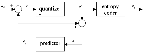
Fig 2. DPCM coder (recei
%3c/h4%3e%20%20%3ch3%3e%3cu%3eDescription%20of%20DPCM%20transmitter%20-%20receiver:%3c/u%3e%3c/h3%3e%20%20%3cp%3e%3cimg%20src=) - sampled values of input signal
- sampled values of input signal
 - prediction error, difference between actual and predicted value
 -
quantized prediction error
-
quantized prediction error
 - predicted value
 - reconstructed value of sampled signal
 - value after DPCM coding (input value for DPCM decoding)
 - predictor coefficients (weighting factors)
 is current sample and
is predicted value, predicted value is formed using prediction factors and
previous samples, usually linear prediction is used, so predicted value can be
given as a weighed linear combination of p previous samples
using , weighting
factors:
is current sample and
is predicted value, predicted value is formed using prediction factors and
previous samples, usually linear prediction is used, so predicted value can be
given as a weighed linear combination of p previous samples
using , weighting
factors:

Difference signal is then: 
We choose weighting factors
in order to minimize some function of error between
and
(like mean-squared) this leads us to the minimization of quantization noise (better
signal-to-noise ratio).
DPCM compression of images and video signals
DPCM conducted on signals with correlation between successive samples leads
to good compression ratios.
Images and video signals are examples of signal which have above mentioned
correlation. In images this means that there is a correlation between the
neighboring pixels, in video signals correlation is between the same pixels in
consecutive frames and inside frames (which is same as correlation inside
image).
Formally written, DPCM compression method can be conducted for intra-frame
coding and inter-frame coding. Intra-frame coding exploits spatial redundancy
and inter-frame coding exploits temporal redundancy.
In the intra-frame coding the difference is formed between the neghboring
pixels of the same frame, while in the inter-frame coding it is formed between
the value of the same value in two consecutive frames. In both coding intra-
and inter- frame the value of target pixel is predicted using the
previously-coded neighboring pixels.
If we apply facts mentioned in DPCM description and Fig 1. and Fig 2. on
image compression
is the current pixel value and
is formed using p pixels prior to current pixel.
is differential image formed as difference beteween actual pixel and previos
pixels (as described above for any signal).
It is important to point out that in forming a prediction reciever i.e
decoder has access only to reconstructed pixel values ,
since the process of quantization of differential image introduces error,
reconstructed values, as expeceted diverges from the original values.
Identical predictions of both receiver and transmitter are assured by
transmitter configuration in which transmitter bases its prediction on the
same values as receiver i.e predicted values. The facts that were mentioned in
this paragraph are applicable to signals in general not just image and video
signals.
Design of DPCM system means optimizing the predictor and quantizer
components, because the quantizer is included in prediction loop there is
complex dependancy between the prediction error and quantizaton error so joint
optimization should be performed to assure optimal results. But, modeling such
optimization is very complex so optimization of those two components are
usually optimized separately. It has been shown that under the mean-squared
error optimization criterion, apart constructions of quantizatior and
predictor are good approximations of joint optimization. Same as in the
previous paragraph, facts in this paragraph are also applicable to signals in
general.
Delta modulation
Delta modulation (DM )is a subclass of differential pulse
code modulation. It can be viewed as a simplified variant of DPCM, in which
1-bit quantizer is used with the fixed first order predictor, and was
developed for voice telephony applications.
Principle of DM : DM output is 0 if waveform falls in value, 1 represents rise
in value, each bit indicates direction in which signal is changing (not how
much), i.e. DM codes the direction of differences in signal amplitude instead
of the value of difference (DPCM).
Basic concept of delta modualation can be explained in the DM block diagram
shown in Fig 3.
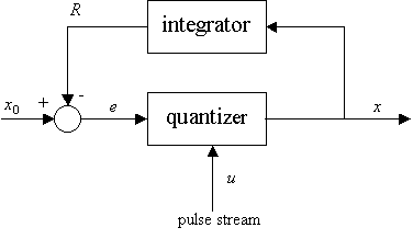
Fig 3. DM encoder
Input signal  is compared to the integrated output
  and delta signal
  (difference between the input signal and the pulse signal) is brought to
quantizer. Quantizer generates output
(difference between the input signal and the pulse signal) is brought to
quantizer. Quantizer generates output  according to difference signal
if difference signal is positive quantizer generates positive impulse, and if
the difference is negative quantizer generates negative signal. So, output
signal
contains bipolar pulses.
according to difference signal
if difference signal is positive quantizer generates positive impulse, and if
the difference is negative quantizer generates negative signal. So, output
signal
contains bipolar pulses.
As it can be noticed in DM there is a feedback by which the output signal
is brought to the integrator which integrates and the bipolar pulses forming a
pulse signal
which is being compared to the input value. Comparisson is conducted between
signal value in n-1 time interval and input signal value
in n time interval, the result is a delta signal .
Delta signal can be positive or negative and then (as described above) the
output signal is formed. The output signal contains information about sign of
signal change for one level comparing to previous time interval.
Important chacteristic of DM is that waveform that is delta modulated needs
oversampling i.e. signal must be sampled faster than necessary, sampling rate
for DM is much higher than Nyquist rate (twice bandwidth). But, at any
sampling rate two types of distortion limits performance of DM encoder.
These distortions are: slope overload distortion and granular
noise.
Slope overload distorsion - is caused by use of step size delta which
is too small to follow portions of waveform that has a steep slope.
Can be reduced by increasing the step size.
Granular noise - is caused by too large step size in signal parts with
small slope. It can be reduced by decreasing the step size.
An illustration of DPCM's advantages over PCM
A typical example of a signal good for DPCM is a line in a continuous-tone
(photographic) image which mostly contains smooth
tone transitions. Another example would be an audio
signal with a low-biased frequency spectrum.
For illustration, we present two histograms made from the same picture
which were coded in two ways. The histograms show the PCM and DPCM sample
frequencies, respectively.
On the first histogram(Fig 4.), a large number
of samples has a significant frequency and we cannot pick only a few of them
which would be assigned shorter code words to achieve compression. On the second
histogram(Fig 5.), practically all the samples are between -20 and +20,
so we can assign short code words to them and achieve a solid compression
rate.
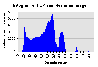
Fig 4. Histogram of PCM sampled image
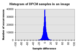
Fig 5. Histogram of DPCM sampled image
DPCM - practical uses
In practice, DPCM is usually used with lossy compression techniques, like
coarser quantization of differences can be used, which leads to shorter code
words. This is used in JPEG and in adaptive DPCM (ADPCM), a common audio
compression method. ADPCM can be watched as a superset of DPCM.
In ADPCM quantization step size adapts to the current rate of change in the
waveform which is being compressed.
Different ADPCM implementations have been studied. The more popular is IMA
ADPCM, this ADPCM implementation is based on the algorithm proposed by Interactive
Multimedia Association. IMA ADPCM standard specifies compression
of PCM from 16 down to 4 bits per sample.
The good side of the ADPCM method is minimal CPU load, but it has significant
quantization noise and only mediocore compression rates can be achieved(4:1).